| Home |
| Search |
| Today's Posts |
 |
|


Menu
| Home Repair (alt.home.repair) For all homeowners and DIYers with many experienced tradesmen. Solve your toughest home fix-it problems. |
| Reply |
|
|
LinkBack | Thread Tools | Display Modes |
|
|
| Home Repair (alt.home.repair) For all homeowners and DIYers with many experienced tradesmen. Solve your toughest home fix-it problems. |
| Reply |
|
|
LinkBack | Thread Tools | Display Modes |
|
#1

Posted to alt.home.repair
|
|||
|
|||
|
Opened up a dehumidifier and seem to have a shorted compressor? There
are three connector pins on the top of the compressor and I'm guessing that NONE of them should show any continuity to the case, right? Thanks. |
|
#2
Posted to alt.home.repair
|
|||
|
|||
|
On 6/19/2013 6:45 PM, Davej wrote:
Opened up a dehumidifier and seem to have a shorted compressor? There are three connector pins on the top of the compressor and I'm guessing that NONE of them should show any continuity to the case, right? Thanks. If any of the pins show continuity to the can, the coils are shorted and compressor is bad. ^_^ TDD |
|
#3
Posted to alt.home.repair
|
|||
|
|||
|
Yes? That is agreeable? NONE of the three
pins under the cover? Should have continuity to the case? .. Christopher A. Young Learn more about Jesus www.lds.org .. .. "Davej" wrote in message ... Opened up a dehumidifier and seem to have a shorted compressor? There are three connector pins on the top of the compressor and I'm guessing that NONE of them should show any continuity to the case, right? Thanks. |
|
#4
Posted to alt.home.repair
|
|||
|
|||
|
How about if all three short to can?
.. Christopher A. Young Learn more about Jesus www.lds.org .. .. "The Daring Dufas" wrote in message ... If any of the pins show continuity to the can, the coils are shorted and compressor is bad. ^_^ TDD |
|
#5
Posted to alt.home.repair
|
|||
|
|||
|
On Jun 19, 6:45*pm, Davej wrote:
Opened up a dehumidifier and seem to have a shorted compressor? There are three connector pins on the top of the compressor and I'm guessing that NONE of them should show any continuity to the case, right? Thanks. Isn't it likely that there are one hot lead and one neutral lead, and one safety/ground????? Assuming that it is a 120V circuit!!! |
|
#6
Posted to alt.home.repair
|
|||
|
|||
|
" wrote:
On Jun 19, 6:45 pm, Davej wrote: Opened up a dehumidifier and seem to have a shorted compressor? There are three connector pins on the top of the compressor and I'm guessing that NONE of them should show any continuity to the case, right? Thanks. Isn't it likely that there are one hot lead and one neutral lead, and one safety/ground????? Assuming that it is a 120V circuit!!! Any experts here ? I don't see many good answers. Greg |
|
#7
Posted to alt.home.repair
|
|||
|
|||
|
gregz wrote:
" wrote: On Jun 19, 6:45 pm, Davej wrote: Opened up a dehumidifier and seem to have a shorted compressor? There are three connector pins on the top of the compressor and I'm guessing that NONE of them should show any continuity to the case, right? Thanks. Isn't it likely that there are one hot lead and one neutral lead, and one safety/ground????? Assuming that it is a 120V circuit!!! Any experts here ? I don't see many good answers. Greg One of several on youtube, this is for a 220V system http://www.youtube.com/watch?v=4RfepFb1Dx8 |
|
#8
Posted to alt.home.repair
|
|||
|
|||
|
On 6/19/2013 9:45 PM, gregz wrote:
" wrote: On Jun 19, 6:45 pm, Davej wrote: Opened up a dehumidifier and seem to have a shorted compressor? There are three connector pins on the top of the compressor and I'm guessing that NONE of them should show any continuity to the case, right? Thanks. Isn't it likely that there are one hot lead and one neutral lead, and one safety/ground????? Assuming that it is a 120V circuit!!! Any experts here ? I don't see many good answers. Greg The three pins on most single phase compressors are "C" Common, "S" Start and "R" Run. The power is hooked to C and R. The capacitor or start relay is hooked to S with the other side of the capacitor connected to R. The neutral is hooked to C common and line to R run. If it's a 120vac compressor there may be a start relay connected so you should follow the wiring diagram. Some units may have two capacitors that are connected to the R run terminal through a start relay with a start capacitor and a run capacitor. There is usually a wiring diagram on a panel cover or on the insulated cover for the terminals on the compressor. ^_^ TDD |
|
#9
|
|||
|
|||
|
TDD is correct, those three pins are are connections to the start winding, the run winding and the common, and if you're getting continuity between any of those pins and the housing of the compressor, it's toast.
But, I had trouble following what gets connected to what in TDD's post, so I'll explain it so that it's easy to understand, and the newbies in here will understand induction motors for the very simple machines they really are. Take a look at this representation of a typical induction motor:  That thing you're looking at is called a "stator". It's what generates a rotating magnetic field so that a compass needle held inside that stator would spin so that it followed that rotating magnetic field. Note that one wire wraps around both vertical poles, and a second wire wraps around the two horizontal poles of that stator. One wire is called the "start winding" and the other is called the "run winding". In actuality, in a real induction motor, both ends of both windings are connected together (kinda) so that when you plug the motor in, both motor windings get the same voltage sine wave applied to them at the same time. Since it's not necessary to show that each winding is wound around a pole on each side of the stator, a schematic diagram of that stator would look like this:  If you imagine that the centrifugal switch isn't there, then you immediately see that both windings have their ends connected to each other, and so when you plug the motor in, both windings would be energized by the same voltage sine wave at the same time. And those three pins should be labeled "S" for start, "R" for run, and "C" for common. The S pin will connect to a point on the top right corner of the previous diagram where the end of the start winding is, the R pin will connect to the bottom left corner of the diagram where the end of the run winding is, and the C pin will connect to the top left corner of the diagram where the start and run windings connect together. To test this kind of a motor, you should find that the resistance between the start pin and the common pin added to the resistance between the run pin and the common pin adds up to the resistance between the start pin and the run pin. And, you are correct, there should be no continuity between any of the pins and the motor housing. The preceding discussion presumes that the motor in your dehumidifier is a "split phase" motor that uses different kinds of wire for each winding. One winding will use a large number of turns of very thin wire whereas the other will use a much smaller number of turns of a very thick wire. Because of the different impedances of those totally different kinds of coils of wire, one kind of coil will develop it's magnetic field earlier than the other when the same 120VAC 60 Hz voltage sine wave is applied to them both. As a result of one winding developing it's magnetic field earlier than the other, an observer in the middle of the stator would see what appears to be a rotating magnetic field. And, if that observer happened to be the magnetic needle in a compas, it would rotate with that rotating magnetic field at 60 cycles per second, or 3600 rpm. In fact, the way the electric motor depicted above would work is that power would be applied to the TWO electric wires going to the motor. The winding that uses many turns of thin wire would develop it's magnetic field first, with the winding on one side of the stator being North and the winding on the other side being South. Then, the winding with fewer turns of thick wire would develop it's magnetic field with the winding on one side of the stator being north and the winding on the opposite side of the stator being south. Then the first winding would reverse it's polarity so that the formerly south pole is now north, and vice versa. And, then the same switch happens in the second winding. and that whole sequence happens over and over and over again at a rate of 60 times per second. So, a compass needle in the middle of that stator would spin around and around, always pointing to which ever winding happened to be north at the time. After about a half a second, the motor gets up to about 3/4 of it's full speed, and the centrifugal switch trips and cuts the start winding out of the circuit so that the motor keeps turning on the run winding alone. NOW, the electric motors in air conditioners, fridges, freezers an dehumidifiers are turning compressors so they need high starting torque, and you can get higher starting torque by using a capacitor to cause the magnetic field of one winding to develop earlier than the other, like this: 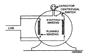 or http://lh4.ggpht.com/_X6JnoL0U4BY/S1...jpg?imgmax=800 That's because a capacitor is essentially just two plates that are close together, and an electric voltage applied to one plate causes electrons to be repelled and a tiny current to flow out of the OTHER plate. In fact, if you apply a sine wave voltage signal to the first plate, the current out the other plate will be at a maximum with the rate of CHANGE of voltage in the first plate is at a maximum, and that actually happens when the voltage sine wave's value goes from negative to positive or from positive to negative. That is, the current out of a capacitor is at a maximum when the applied sine wave voltage has zero value. Similarily, when the current out the second plate will be at a minimum when the rate of change of voltage in the first plate is zero, and that actually happens when the voltage sine wave's value is at a maximum or a minimum voltage. That is, current out of a capacitor is at a minimum when the applied sine wave voltage is at a maximum positive or negative value. Thus, instead of making the start and run windings out of different kinds of wire, you can make them out of the same kind of wire, but put a capacitor in series with one of the windings. The capacitor will cause the current sine wave going through that branch of the circuit to be 90 degrees out of phase with the current sine wave going through the other winding, even though the same voltage sine wave is applied to both branches!. And, since the magnetic field of the winding develops in lock step with the current through the winding, one winding in a "capacitor start" motor will develop it's magnetic field 90 degrees on the applied voltage sine wave graph earlier than the other winding, making for a better designed electric motor. But, since that capacitor can't be serviced inside a hermetically sealed motor, it's necessary to put the capacitor on the outside of the motor so that it can be replaced if it ever goes bad. So, what we have is a capacitor that changes the timing of the magnetic field development in the start winding for about 1/2 of a second each time the motor starts. After that half second, the motor comes up to speed and the centrifugal switch trips both the start winding and it's capacitor out of the circuit. From then on, the motor just turns on the run winding alone. And, for decades, that was the way all capacitor start motors worked. And then someone got a bright idea. Since there's no law saying that you have to put the capacitor on the same circuit as the start winding is on, why not put a capacitor on the run winding so that the capacitor is in the circuit ALL of the time instead of only a tiny fraction of the time. Doing that would allow you to tweak the capacitor capacity, and thereby hopefully make the magnetic field of the run winding develop at the optimum time so that the motor runs the smoothest and the most efficiently. And, that is why we now have "capacitor run" motors as well as "capacitor start" motors. Capacitor run motors have a "run capacitor" in series with the run winding instead of a "start capacitor" in series with the start winding. And, if you have a capacitor run motor that runs smoothly and efficiently, it only makes sense now to put another capacitor on the start winding so that you can also tweak it to maximize starting torque. So, now you can buy "capacitor start capacitor run" motors that have different kinds of capacitors on each winding that provide greater starting torque and run more smoothly and efficiently than the old capacitor start motors did, and that helps make newer appliances more efficient than the appliances built 20 years ago. There, now you know more about the basics of induction motors than 99 percent of home owners. Last edited by nestork : June 20th 13 at 08:07 AM |
|
#10
Posted to alt.home.repair
|
|||
|
|||
|
No, it's not likely.
Sorry, meant to write NO!!!!! It's NOT likely!!!!!! .. Christopher A. Young Learn more about Jesus www.lds.org .. .. wrote in message ... On Jun 19, 6:45 pm, Davej wrote: Opened up a dehumidifier and seem to have a shorted compressor? There are three connector pins on the top of the compressor and I'm guessing that NONE of them should show any continuity to the case, right? Thanks. Isn't it likely that there are one hot lead and one neutral lead, and one safety/ground????? Assuming that it is a 120V circuit!!! |
|
#11
Posted to alt.home.repair
|
|||
|
|||
|
Dufas and I repair these things for a living. Dehumidifier compressor should have a cover on the side, which contains a start relay and an overload protector. These can be pulled off the electrical pins. None of the three pins should have continuity to the tin can, the copper tubing, or the electrical ground on the plug.
.. Christopher A. Young Learn more about Jesus www.lds.org .. .. "gregz" wrote in message ... Isn't it likely that there are one hot lead and one neutral lead, and one safety/ground????? Assuming that it is a 120V circuit!!! Any experts here ? I don't see many good answers. Greg |
|
#12
Posted to alt.home.repair
|
|||
|
|||
|
Some have a relay, and no capacitors. Most have an overload protector on the common pin.
.. Christopher A. Young Learn more about Jesus www.lds.org .. .. "The Daring Dufas" wrote in message ... The three pins on most single phase compressors are "C" Common, "S" Start and "R" Run. The power is hooked to C and R. The capacitor or start relay is hooked to S with the other side of the capacitor connected to R. The neutral is hooked to C common and line to R run. If it's a 120vac compressor there may be a start relay connected so you should follow the wiring diagram. Some units may have two capacitors that are connected to the R run terminal through a start relay with a start capacitor and a run capacitor. There is usually a wiring diagram on a panel cover or on the insulated cover for the terminals on the compressor. ^_^ TDD |
|
#13
Posted to alt.home.repair
|
|||
|
|||
|
On Wednesday, June 19, 2013 7:45:04 PM UTC-4, Davej wrote:
Opened up a dehumidifier and seem to have a shorted compressor? There are three connector pins on the top of the compressor and I'm guessing that NONE of them should show any continuity to the case, right? Thanks. You've got a short. It's shot. The winding resistances are so low that a single short on any winding will look like all three connectors are shorted. |
|
#14
Posted to alt.home.repair
|
|||
|
|||
|
"Stormin Mormon" wrote:
Dufas and I repair these things for a living. Dehumidifier compressor should have a cover on the side, which contains a start relay and an overload protector. These can be pulled off the electrical pins. None of the three pins should have continuity to the tin can, the copper tubing, or the electrical ground on the plug. . Christopher A. Young Learn more about Jesus www.lds.org . . "gregz" wrote in message ... Isn't it likely that there are one hot lead and one neutral lead, and one safety/ground????? Assuming that it is a 120V circuit!!! Any experts here ? I don't see many good answers. Greg Trying to remember what was said in the book. I know the resistance is suppose to be very high. A high resistance might be overcome with line voltage. Any current from case to any terminal might be a better test, but a short is a short. Greg |
|
#15
Posted to alt.home.repair
|
|||
|
|||
|
On Thu, 20 Jun 2013 16:27:23 +0000 (UTC), gregz
wrote: "Stormin Mormon" wrote: Dufas and I repair these things for a living. Dehumidifier compressor should have a cover on the side, which contains a start relay and an overload protector. These can be pulled off the electrical pins. None of the three pins should have continuity to the tin can, the copper tubing, or the electrical ground on the plug. . Christopher A. Young Learn more about Jesus www.lds.org . . "gregz" wrote in message ... Isn't it likely that there are one hot lead and one neutral lead, and one safety/ground????? Assuming that it is a 120V circuit!!! Any experts here ? I don't see many good answers. Greg Trying to remember what was said in the book. I know the resistance is suppose to be very high. A high resistance might be overcome with line voltage. Any current from case to any terminal might be a better test, but a short is a short. Greg Disconnect all three wires from the compressor, and read resistance from the connectors on compressor to its case. Some times the short is in the capacitor circuit or elsewhere. There should not be any reading from the compressor's connectors to the case. |
|
#16
Posted to alt.home.repair
|
|||
|
|||
|
Please make note of where the wires go. Not always easy to remember. This I know from experience. Digital pictures are useful.
.. Christopher A. Young Learn more about Jesus www.lds.org .. .. wrote in message ... Disconnect all three wires from the compressor, and read resistance from the connectors on compressor to its case. Some times the short is in the capacitor circuit or elsewhere. There should not be any reading from the compressor's connectors to the case. |
|
#17
Posted to alt.home.repair
|
|||
|
|||
|
On Friday, June 21, 2013 4:41:17 PM UTC-5, Stormin Mormon wrote:
Please make note of where the wires go. Not always easy to remember. This I know from experience. Digital pictures are useful. Thanks all, the unit is indeed kaput. |
| Reply |
| Thread Tools | Search this Thread |
| Display Modes | |
|
|
 Similar Threads
|
||||
| Thread | Forum | |||
| continuity tester ? | Electronic Schematics | |||
| continuity tester ? | Electronics | |||
| continuity tester ? | Electronics Repair | |||
| Continuity checker - where to buy? | UK diy | |||
| Continuity tester | UK diy | |||


 Linear Mode


